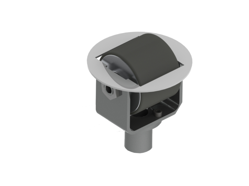
Smart Roller Motor
Smart roller motor is designed for balance wheel sorting system with two kinds of product: high speed version (software V27) and low speed version( software V4.6)
Main Technical Data of Smart Roller Motor

Dimension Drawing of Smart Roller Motor

Main Technical Data of Driver Card

Driver in IO working mode: running & stop are controlled via DIP switch is used to configure operating speed at either low and high as well as rolling directions.
Driver adopts RS 485 as communication port: speed and direction are controlled via trunk.
Driver is designed as 1-4, 1 set of driver runs 4 smart rollers.
Driver Dimension


Driver Card Port Description

Control Signal Description

Note 1: INPT1 and INPT2 schematic diagram is as below:

INPT1/INPT2 receives DC48 or DC24V signals, please input DC 48V when use DC48V signal as driver is powered by 48V. Please connect GND and CM with wire or directly connect to DC48V of main power source (recommended, so as to avoid interference) if user chooses to control via DC24V.
Note: IO mode is prior to RS 485 mode in running, that is, please refer to the below table to stop running IO mode or to suspend IO port.
INPT True Value Table

DIP Switch
The definition of DIP switch is different in IO mode and RS485 mode, please read the table as below, ON stands for valid, OFF stands for invalid.
Port Definition

DIP-Switch-RS485 Mode

Motor Port
Motor Port Definition

Power Supply Port
Power Side Port


